Minecraft logic gates are redstone circuits that give different outputs based on their own rules. For example, the output from an AND gate will only be active (turned on) when both its inputs are active.
NOT gates
A NOT gate will invert the input it gets. So if you connect the input with a lever, turning the lever on will cause the NOT gate to output a signal that is turned off.

AND gates
An AND gate takes two inputs and will only send an active signal if both inputs have been activated. So if you’ve connected both inputs to a lever, turning on just one lever will not activate the mechanism connected to the AND gate’s output.

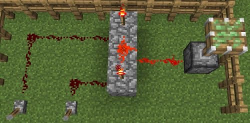
NAND gates
A NAND gate is basically the NOT gate equivalent of the AND gate. Instead of sending an active signal when both its inputs are active, the NAND gate will deactivate the signal its sending out. Turning on just 1 level will not deactivate the mechanism connected to the NAND gate’s output.
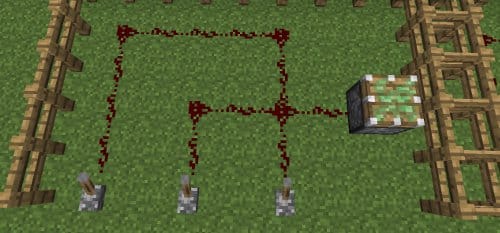
OR gates
This is very easy to figure out by just looking at the picture. If any of the inputs are turned on, the mechanism connected to them will also turn on. Only when all of the inputs have been turned off will the mechanism turn off.
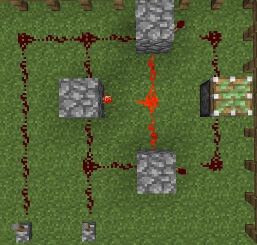
NOR gates
The NOR gate is almost the exact opposite of the OR gate. If any of the inputs are turned on, the mechanism connected to them will turn off. Only when all of the inputs have been turned off will the mechanism turn on.

XOR gates
The XOR gate will only send out an active signal when only 1 of its inputs is active (when both inputs are different). If both its inputs are activated or deactivated, the mechanism connected to the XOR gate will also be deactivated.
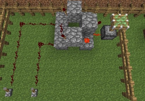
XNOR gates
The XNOR gate will only send out an active signal when both its inputs are the same (on or off). If just one of the inputs is active, the mechanism connected to the XNOR gate’s output will deactivate.

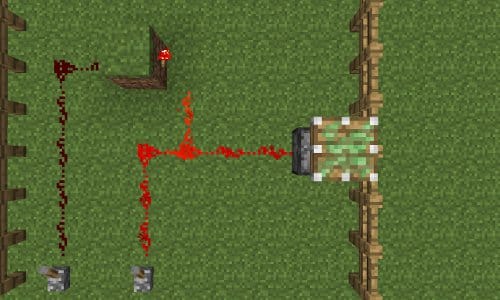
IMPLY Gates
The IMPLY gate is a bit tricky to understand fully. You can see it as a master switch and a child switch. In the example below, lever A is the master switch. Turning A on will deactivate the piston, and turning it off will activate it. However, as long as lever A is turned off, lever B will not function. Once lever A has been activated, lever B can turn the piston on and off.
We can make it a little more complicated like this:
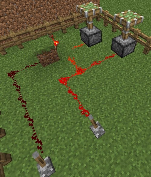
In the picture above, we’ve added another piston. As long as lever B is turned off, lever A can turn both pistons on and off simultaneously. But when lever B is turned on, lever A can only turn piston one on and off. The old rules for lever B are still true. Lever B can only turn piston two on and off, but only if lever A is turned on.